Control HC-05 Bluetooth Module with PIC16F877A using MPLAB X
Controlling HC-05 Bluetooth Module with PIC16F877A using MPLAB X and XC8
🧰 Hardware Required
-
PIC16F877A microcontroller
-
HC-05 Bluetooth module
-
5V power supply
-
UART to USB Converter (for PC debugging)
-
LED (for output demonstration)
-
10k resistor x 2 (for voltage divider on HC-05 RX pin)
-
Breadboard, jumper wires
🧠 Overview
We’ll send commands from a Bluetooth terminal (e.g., Android app like "Serial Bluetooth Terminal") to the
PIC16F877A via HC-05. For example, sending "ON" will turn on an LED, and "OFF" will turn it off.
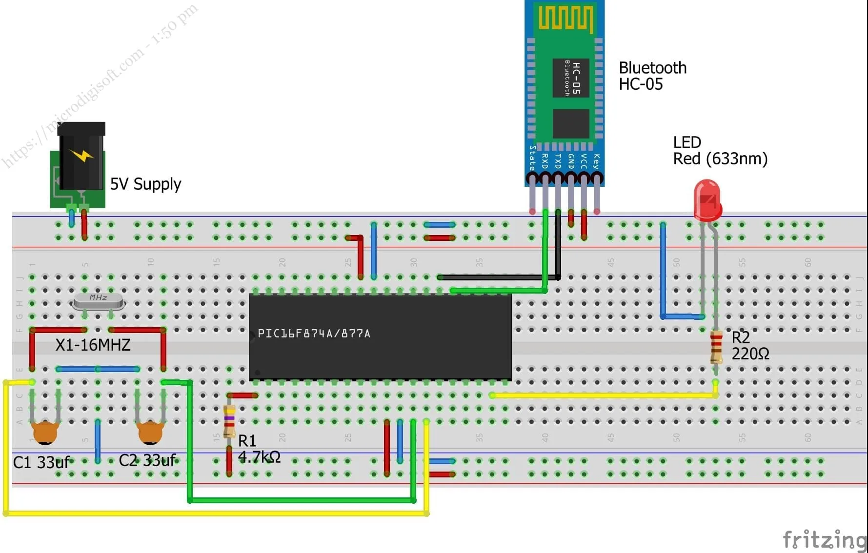
🔌 Circuit Diagram
HC-05     ->    PIC16F877A
----------------------------
TX        ->    RC7/RX (pin 26)
RX        ->    RC6/TX (pin 25) via voltage divider
VCC       ->    5V
GND       ->    GND

LED + Resistor -> RB0 (pin 33)
⚠️ IMPORTANT: HC-05 RX pin is 3.3V tolerant only. Use a voltage divider from PIC TX (RC6) to HC-05 RX.
⚙️ MPLAB X Project Setup
Step 1: Create a New Project
-
Open MPLAB X → New Project → Standalone Project
-
Choose device:
PIC16F877A -
Choose tool (e.g., PICkit 3 or Simulator)
-
Compiler:
XC8
Step 2: UART Initialization Code
Create a new source file named main.c and paste the following code:
#define _XTAL_FREQ 20000000  // 20 MHz crystal

#include

// CONFIG
#pragma config FOSC = HS        // High-speed oscillator
#pragma config WDTE = OFF       // Watchdog Timer disabled
#pragma config PWRTE = OFF
#pragma config BOREN = OFF
#pragma config LVP = OFF
#pragma config CPD = OFF
#pragma config WRT = OFF
#pragma config CP = OFF

// UART Initialization
void UART_Init(void) {
    TRISC6 = 0; // TX as output
    TRISC7 = 1; // RX as input

    SPBRG = 129; // Baud rate 9600 for 20MHz (Formula: SPBRG = (Fosc / (64 * Baud)) - 1)
    BRGH = 0;    // Low speed
    SYNC = 0;    // Asynchronous
    SPEN = 1;    // Enable serial port

    TXEN = 1;    // Enable transmission
    CREN = 1;    // Enable continuous reception
}

// Send a character
void UART_TxChar(char ch) {
    while (!TXIF);
    TXREG = ch;
}

// Send a string
void UART_TxString(const char *str) {
    while (*str != '\0') {
        UART_TxChar(*str++);
    }
}

// Read a character
char UART_RxChar(void) {
    while (!RCIF);
    return RCREG;
}

// Compare input string
int compareCmd(const char *received, const char *cmd) {
    for (int i = 0; cmd[i] != '\0'; i++) {
        if (received[i] != cmd[i]) return 0;
    }
    return 1;
}
Step 3: Main Application Logic
Add the following inside main():
void main() {
    char buffer[10];
    char ch;
    int i = 0;

    TRISB0 = 0;     // LED pin as output
    PORTBbits.RB0 = 0;

    UART_Init();    // Initialize UART

    UART_TxString("Ready to receive...\r\n");

    while (1) {
        if (RCIF) {
            ch = UART_RxChar();

            if (ch == '\n' || ch == '\r') {
                buffer[i] = '\0';  // Terminate string

                if (compareCmd(buffer, "ON")) {
                    PORTBbits.RB0 = 1;
                    UART_TxString("LED ON\r\n");
                } else if (compareCmd(buffer, "OFF")) {
                    PORTBbits.RB0 = 0;
                    UART_TxString("LED OFF\r\n");
                } else {
                    UART_TxString("Unknown Command\r\n");
                }
                i = 0;  // Reset index
            } else if (i
🧪 Testing the Project
-
Build the project (
Clean and Build) -
Upload the hex file to PIC16F877A
-
Open a Bluetooth terminal app on your phone
-
Pair with the HC-05 (default password:
1234) -
Connect and send:
-
ON→ LED turns on -
OFF→ LED turns off
-
🛠️ Troubleshooting Tips
-
Ensure baud rate in mobile app matches
9600 -
HC-05 must be in Data Mode (not AT mode)
-
Double check voltage divider for HC-05 RX
-
Use an external 20MHz crystal and proper MCLR reset circuit for stability
📝 Conclusion
You’ve successfully learned how to:
-
Initialize UART on PIC16F877A
-
Communicate with HC-05 over Bluetooth
-
Control external hardware like an LED based on Bluetooth commands
📎 Optional Enhancements
-
Use interrupts for UART RX
-
Add more commands (e.g.,
"BLINK","STATUS") -
Display data on LCD/OLED
-
Send sensor data to mobile app
Comments (0)
No comments yet. Be the first to comment!
Leave a Comment